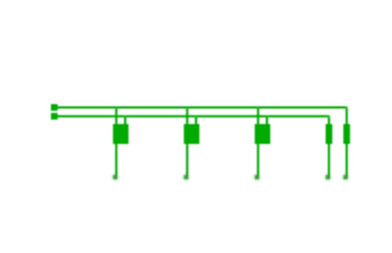
Shows the usage of basic gates like AND, OR, XOR and NOT.
Also uses switches for input and LEDs for output. Click on a switch (square with "0") to toggle.
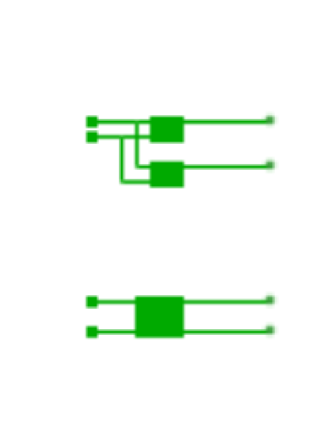
A half adder adds two bits. The output bit "s" is the sum, "c" is the carry.
You can either build a half adder using two basic gates or you just use the half adder element.
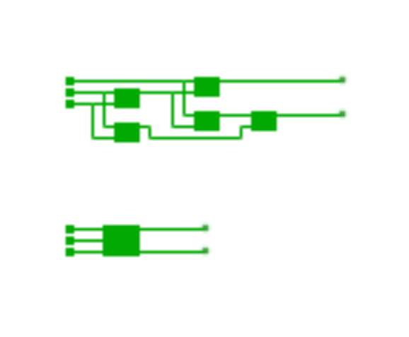
The full adder does the same as the half adder, but can add three bits.
In case all three input connectors are set to HIGH (1) the sum and carry output would also be HIGH (1).
You can build a full adder using two half adders and an OR gate. Or just use the full adder element.
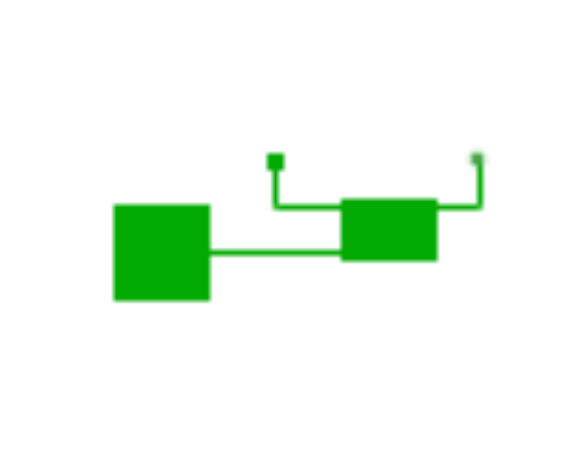
A D-Latch can (like other latches/flip-flops) hold a state. It can save a single bit.
D-Latches have one input connector for data and one clock connector. On falling edge the new value gets stored. In simulation mode you can emit clock signals using the clock controls on the left side.
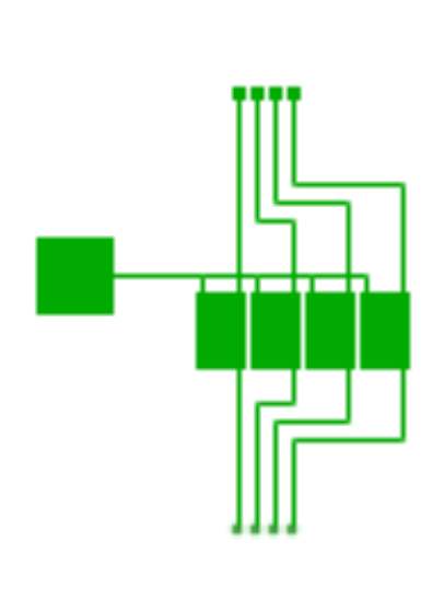
You can build a simple 4-bit register using 4 d-latches. In this sample all latches are controlled by the same clock signal.
Open sample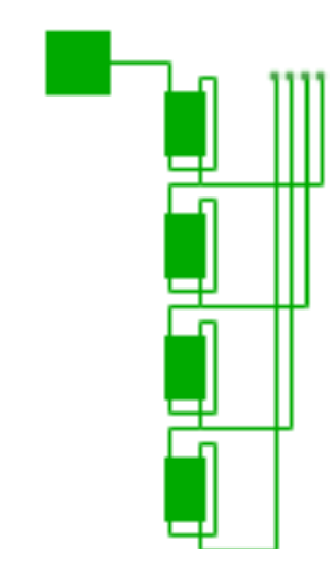
A binary counter increases its output value by one on each clock tick. In this sample 4 d-latches are used.
Only the first latch is connected to the clock, the other ones are using the output of the previous latch as clock signal.
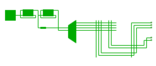
In this sample a diode matrix is used to map from 4 different traffic light phases (red, red-yellow, green, yellow) to the proper light.
A diode only let signals pass from horizontal to vertical wires.
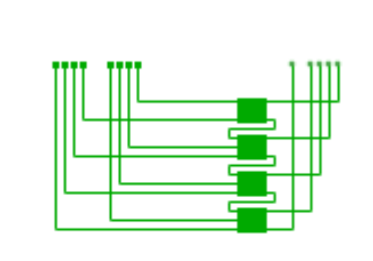
Adds two 4-Bit numbers. All carry bits are passed to the next full adder. The last carry bit (integer overflow) is the shown next to the output.
Open sample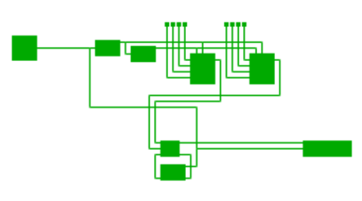
Like the previous sample, but serial implementation. A 2-bit counter with multiplexer selects the correct input bits. Afterward both bits gets added to the previous carry bit and the result is saved in a shifting register.
Open sample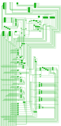
A simple 4-bit CPU with 12 instructions. You can find a manual on the board. The initial program stored in the ROM (which is a diode matrix) just counts upwards. To start the CPU generate a continuous clock signal. If the simulation is too slow, just deactivate the frame/logic tick synchronization.
Open samplePlease read the terms of use first.
You can share a snapshot of the current board which is represented by a unique URL.
Snapshots are editable, but can only get saved as new snapshot or as fork.

You can create a copy of this board in your workspace. You will be the owner of the board and can set up your own team of collaborators.

Changes in the new board will not affect the forked one.
We are sorry, an unexpected error occurred.
Error Code:
Message:
Please reload the page. If this error still occurs, contact the support.